Charger of Electric Car: Inside the Hardware and How It Works
A charger of electric car looks like a simple box, but inside it is a coordinated system of electrical, electronic and mechanical parts. Understanding what those parts are — and how they cooperate — explains why some units last a decade while others fail early, and why certain features cost more. This technical breakdown opens the enclosure and walks through each subsystem, from the shell to the safety sensors.
The Enclosure and Ingress Protection
The outer shell is the first line of defence. Rated by an IP (ingress protection) code, it keeps dust and water away from live parts — IP54 suits sheltered spots, while IP65 or higher is expected for fully exposed outdoor bollards. The enclosure also manages heat and provides the mechanical strength to resist impact and tampering. Material choice, usually polycarbonate or powder-coated metal, affects both weathering and the unit's long-term appearance.
AC and DC Side Circuitry
Inside, the circuitry splits into an AC side and a DC side. On an AC charger, the AC side carries grid power through a contactor, a residual-current monitor and relays that only close once the vehicle is authenticated and safe. On a DC charger, the AC side feeds the power modules, while a separate DC side handles the high-voltage output to the vehicle. Contactors, fuses and surge protection here determine how the unit behaves during faults — a frequent root cause of field failures when underspecified.
Power Modules: The Conversion Heart
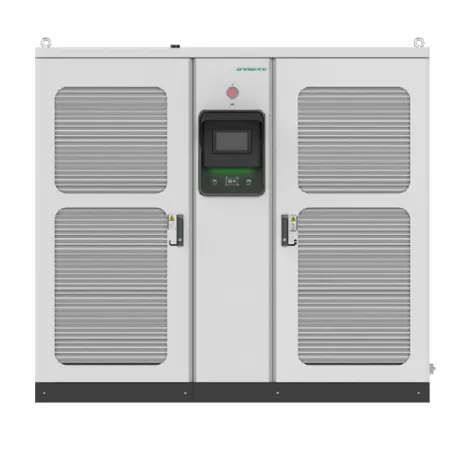
On a DC unit, the power modules are where AC becomes high-voltage DC. They are the most stressed, most expensive and most failure-prone components, which is why modular designs matter: a charger built from several smaller modules can keep running if one fails, and modules can be swapped rather than scrapping the whole cabinet. Gresgying's 120–180kW station and ultra-fast station both rely on this modular thinking, and our modular hub article explains the reliability gain.
Modular vs Monolithic
Modular power stages isolate faults and simplify repair. Industrial custom builds often standardise on this approach for uptime-critical sites.
Controller and Communication (OCPP)
A small controller board runs the show: it manages the charge session, talks to the vehicle over the signalling pilot, and connects to the backend over Ethernet, Wi-Fi or 4G. Support for OCPP (Open Charge Point Protocol) is what lets the hardware work with independent management platforms and future software, rather than locking the operator to one vendor. This is one of the specifications that separates a durable charger of electric car investment from a dead-end purchase.
Metering and Billing Unit
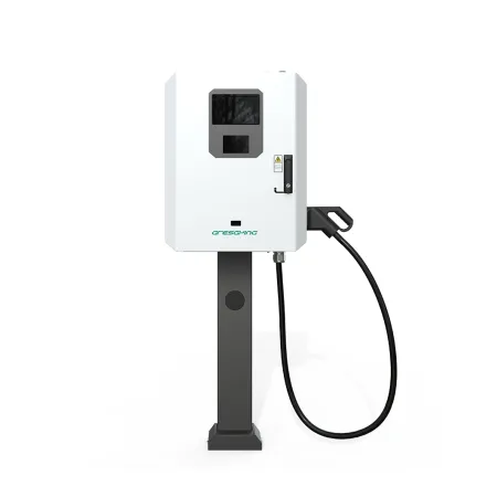
For any shared or public charger, an accurate, certified energy meter is essential — it is what the bill is based on and what reconciles with the grid. The meter sits on the AC or DC side depending on architecture and must be tamper-resistant and calibration-certified in the markets where the unit operates. On a home unit the meter is simpler, used mainly for reporting and solar balancing.
Connector, Cable and Locking
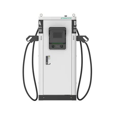
The connector and cable are the only parts the user touches daily, so they wear fastest. A good unit uses a certified connector with a locking actuator that secures the plug to the vehicle during charging, and a cable rated for repeated flexing and outdoor use. On high-power DC, the cable may be liquid-cooled, adding internal channels and sensors. The physical interface also decides protocol compatibility — CCS, CHAdeMO, NACS or GB/T — and Gresgying's CHAdeMO certification is one example of that interface being formally validated.
Safety Protection and Temperature Monitoring
Throughout the unit, sensors watch temperature at the connectors, modules and cable, while the controller enforces limits and cuts power on any anomaly. Residual-current detection, overvoltage and overcurrent protection, and ground-fault monitoring are layered so that no single failure can create a hazard. These protections are also where regional certification is earned; our safety standards guide maps them to compliance, and the high-performance DC spec guide lists which ones matter most at high power.
How the Parts Work Together
In a normal session the controller first authenticates the user and the vehicle, then closes the AC contactor and, on DC units, spins up the power modules. It follows the vehicle's requested current, watches every temperature sensor, records energy through the meter, and only opens the circuit when charging completes or a fault appears. When one subsystem is weak — an undersized contactor, a cheap cable, a non-modular power stage — the whole unit's life and fault rate suffer. That is why a well-engineered wallbox or a robust rapid charger is judged on the quality of every part, not just the headline kilowatt number.
The same logic applies when comparing quotes. Two units with identical kilowatt ratings can have very different internal quality, and the differences only show up after months of daily use. Asking a supplier which modules they use, how the metering is certified and how temperature is monitored is a faster route to a good decision than comparing sticker prices alone.
Rule of thumb: a charger is only as reliable as its weakest subsystem. Modular power, certified metering and thorough temperature monitoring are what separate long-life hardware from early failures.
Conclusion
A charger of electric car is a system, not a single component. The enclosure protects it, the circuitry and power modules do the electrical work, the controller and OCPP keep it connected, the meter makes it accountable, and the sensors keep it safe. Knowing how these parts interact is the best way to judge quality and predict a unit's service life before you buy.
Want Hardware Built to Last?
Talk to Gresgying about modular power, certified metering and the right build for your AC or DC charging site.
Get Your Free Quote →